instrumentation
Centrifuge Selection and g-Force Calculation: RCF, Rotor Radius and Rotor Geometry
A speed in revolutions per minute describes a motor, not a separation. The conversion to relative centrifugal force, why rotor radius makes the same rpm mean different things, and the vial spin-down that protects a powder before the cap comes off.
A protocol that says spin at 10,000 rpm has specified a motor setting and nothing else. The quantity that determines whether anything sediments is the relative centrifugal force, and that depends on the square of the rotational speed multiplied by the radius at which the sample sits. Two instruments running at identical speed with different rotors can differ by a factor of two or more in the force they apply, so the same instruction produces a clean pellet in one laboratory and a cloudy supernatant in another 12. The fix is arithmetic and takes one line, and the reason it is worth insisting on is that the failure is silent: nothing on the instrument reports that the separation did not happen.
Why rpm alone means nothing
Sedimentation is driven by the acceleration experienced by the particle, and in a rotating frame that acceleration is the angular velocity squared multiplied by the distance from the axis of rotation. Speed enters as a square and radius enters linearly, which has two consequences that pull in opposite directions. Doubling the speed quadruples the force, so speed is the dominant control. But radius varies by a factor of two or three across the rotors found in one building, and that factor applies directly.
A benchtop microcentrifuge with a compact rotor may have a radius to the tube base of about 6 to 9 centimetres. A large refrigerated floor instrument with a swing-out rotor may have a radius of 18 to 20 centimetres. Set both to 4,000 rpm and the second applies roughly two to three times the force of the first. Neither display is wrong; they are simply reporting a quantity that is not the one the protocol cares about.
This is why published methods that depend on differential sedimentation increasingly state force, time and rotor geometry together. Comparative work on one preparation across rotor types has shown yield and purity varying with geometry and run time rather than with the nominal setting 1, and a theoretical treatment of the same problem shows that path length and radial position govern what actually pellets — so two runs matched on force alone can still differ 2.
Converting speed to relative centrifugal force
Relative centrifugal force is expressed as a multiple of standard gravity, written as a number followed by g. The working relationship, with radius in centimetres and speed in revolutions per minute, is that RCF equals 1.118 times ten to the power minus five, multiplied by the radius, multiplied by the speed squared. The constant simply carries the unit conversions; the physics is entirely in the radius and the square of the speed.
Rearranged for the other direction, the speed required to reach a target force is the square root of the target divided by the product of the constant and the radius. A worked example makes the dependence concrete. To achieve 3,000 g in a rotor with a radius of 8 centimetres requires about 5,790 rpm. The same 3,000 g in a rotor with a radius of 5 centimetres requires about 7,330 rpm, and in one with a radius of 10 centimetres about 5,180 rpm. Same target, three different dial settings, and only one of the three is written in the protocol if the protocol records rpm.
| Speed | r = 5 cm | r = 8 cm | r = 10 cm | r = 18 cm |
|---|---|---|---|---|
| 3,000 rpm | 503 g | 805 g | 1,006 g | 1,811 g |
| 5,000 rpm | 1,398 g | 2,236 g | 2,795 g | 5,031 g |
| 8,000 rpm | 3,578 g | 5,725 g | 7,155 g | 12,880 g |
| 10,000 rpm | 5,590 g | 8,944 g | 11,180 g | 20,124 g |
| 14,000 rpm | 10,956 g | 17,530 g | 21,913 g | 39,443 g |
Three radii exist for any rotor and they are not interchangeable. The minimum radius is the distance from the axis to the top of the sample column, the maximum radius is the distance to the base of the tube, and the average radius lies between them. Manufacturers quote maximum radius for the headline g figure, because it is the largest number available. A sedimenting particle starting near the meniscus begins its journey at the minimum radius and therefore under a substantially lower force than the quoted maximum, which is one reason a pellet forms progressively rather than all at once, and why run time is part of the specification rather than a detail.
Fixed-angle against swing-out
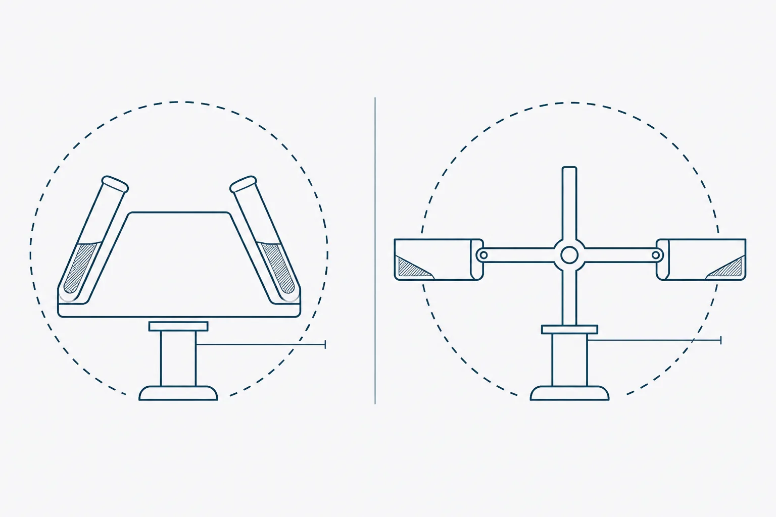
The two common geometries differ in where the pellet lands and in how far a particle must travel to get there. In a fixed-angle rotor the tubes are held at a constant angle, typically between 25 and 45 degrees from the axis. Particles migrate outward, strike the outer wall of the tube, and then slide down it to form a pellet at the side of the tube base. The path from suspension to wall is short, so separations are quick, and the pellet is compact but sits partly up the wall, which makes it easy to disturb when decanting.
In a swing-out rotor the buckets pivot outward to horizontal as the rotor accelerates, so the sedimentation direction runs along the axis of the tube and the pellet forms squarely at the base. The path is longer, so runs take longer at the same force, but the pellet is clean, the boundary between pellet and supernatant is sharp, and the geometry is what density-gradient work requires because the gradient stays perpendicular to the force. Comparative work on the same preparation has found measurable differences in both yield and purity between the two geometries at nominally matched force, which is a direct consequence of path length rather than a defect in either rotor 12.
| Property | Fixed-angle | Swing-out |
|---|---|---|
| Pellet position | Side of the tube, part way up the wall | Squarely at the tube base |
| Sedimentation path | Short; fast at a given force | Long; slower at the same force |
| Maximum speed | Higher; the rotor is a solid mass | Lower; hinged buckets limit it |
| Supernatant recovery | Awkward; the pellet lies in the pouring path | Clean; the pellet is out of the way |
| Density gradients | Unsuitable; the gradient reorients | The correct choice |
| Small volumes and quick spin-downs | The usual choice | Rarely needed |
| Radius variation along the tube | Large; force differs markedly top to bottom | Smaller; the tube lies along the radius |
Balancing, and what an imbalance does
A rotor is balanced by mass, not by volume and not by eye. Two tubes holding the same volume of liquids with different densities are not balanced; two tubes filled to the same visual mark with the same liquid usually are, but only to the precision of the eye, which is not the precision the manual asks for. Balance opposite tubes to within the tolerance stated for that rotor, weigh them together with their caps and their contents, and where an odd number of samples exists, make up a blank with water to the same mass rather than leaving a gap.
- Confirm the rotor is the one the protocol specifies, and that it is seated and locked on the spindle.
- Inspect the rotor and buckets for corrosion, cracks or missing pivot pins before loading, and check that every tube is rated for the intended force.
- Weigh tube pairs on a balance and match them to within the tolerance in the rotor manual, caps included.
- Place matched pairs diametrically opposite each other; for six-position or twelve-position rotors, maintain symmetry across the whole rotor rather than only within one pair.
- Load every bucket of a swing-out rotor, using empty balanced buckets where there is no sample, because the rotor is designed to run with all positions fitted.
- Close the lid, confirm the rotor is free to turn, and start the run only when the interlock has engaged.
- Stay with the instrument through acceleration to full speed, which is when an imbalance declares itself, and abort at the first unusual noise or vibration.
- Let the rotor stop on its own where the separation is delicate; braking hard can resuspend a loose pellet.
An imbalance is a rotating unbalanced mass, and the force it generates scales the same way the separation does — with the square of the speed. A mismatch imperceptible at 1,000 rpm becomes a large cyclic side load at 14,000 rpm. The immediate effects are vibration, noise and wear on the drive bearing, which is why a mistreated centrifuge develops a persistent wobble. The serious case is mechanical failure of the rotor, which is why these instruments are built with interlocked lids and containment specified by an international safety standard, and why the interlock is never defeated 3.
Two habits prevent nearly all of it. Weigh, rather than estimate, whenever a run will exceed a few thousand rpm. And record rotor hours and inspect on the schedule in the manual: rotors have finite lives, aluminium corrodes where salt solutions have been spilled and not rinsed, and a rotor that has been dropped is retired rather than inspected optimistically 3.
Spinning down a vial before opening
The smallest centrifugation in the laboratory is also the one most often skipped. A vial of lyophilised solid that has travelled will have material on the closure, on the shoulder and around the neck, because the cake is light, friable and electrostatically active. Opening the vial without first collecting that material at the base loses it: some leaves with the cap, some becomes airborne, and some stays on the rim where it is neither weighed nor dissolved.
The loss is not trivial in proportion. A vial containing five milligrams that leaves a few hundred micrograms on the closure has lost a percentage-level fraction of the contents, and every concentration computed from the stated fill mass is then wrong by that amount and wrong in the same direction. Adsorptive losses onto container surfaces are a documented and material problem for peptides handled at small scale, and material stranded on a cap is the coarsest version of the same effect 4.
- Equilibrate the sealed vial to ambient temperature before spinning, so that no moisture condenses onto the solid when the cap is eventually removed.
- Spin the sealed vial upright for 10 to 30 seconds at a low force — a few hundred g is ample — using an adapter that supports it properly.
- Never spin an unsupported vial in an oversized rotor position, and never spin a vial whose closure is not secure.
- Tap the vial gently on the bench first where a centrifuge with a suitable adapter is not available; it is less effective but better than nothing.
- Inspect the closure under good light after opening, and treat any visible residue as a quantified loss rather than an inconvenience.
- Repeat the spin-down after any transport, and after any period of storage in which the vial has been inverted or shaken.
The same argument applies after reconstitution, where droplets on the closure and neck are solution that has left the measured volume. A brief spin before the first withdrawal returns them, and one before opening a stored aliquot returns whatever condensed during thawing. Both remove a loss that is otherwise invisible, unrecorded and unidirectional — the worst combination of properties an error can have.
References
- The influence of rotor type and centrifugation time on the yield and purity of extracellular vesicles
- Isolation of exosomes by differential centrifugation: Theoretical analysis of a commonly used protocol
- IEC 61010-2-020:2016 Safety requirements for electrical equipment for measurement, control and laboratory use — Part 2-020: Particular requirements for laboratory centrifuges
- The importance of using the optimal plasticware and glassware in studies involving peptides